Over 70% of new broadband deployments in urban U.S. projects now specify fiber-to-the-home. This fast transition toward full-fiber networks shows the growing need for dependable manufacturing equipment.
Compact Fiber Unit

Fiber Ribbon Line

Compact Fiber Unit
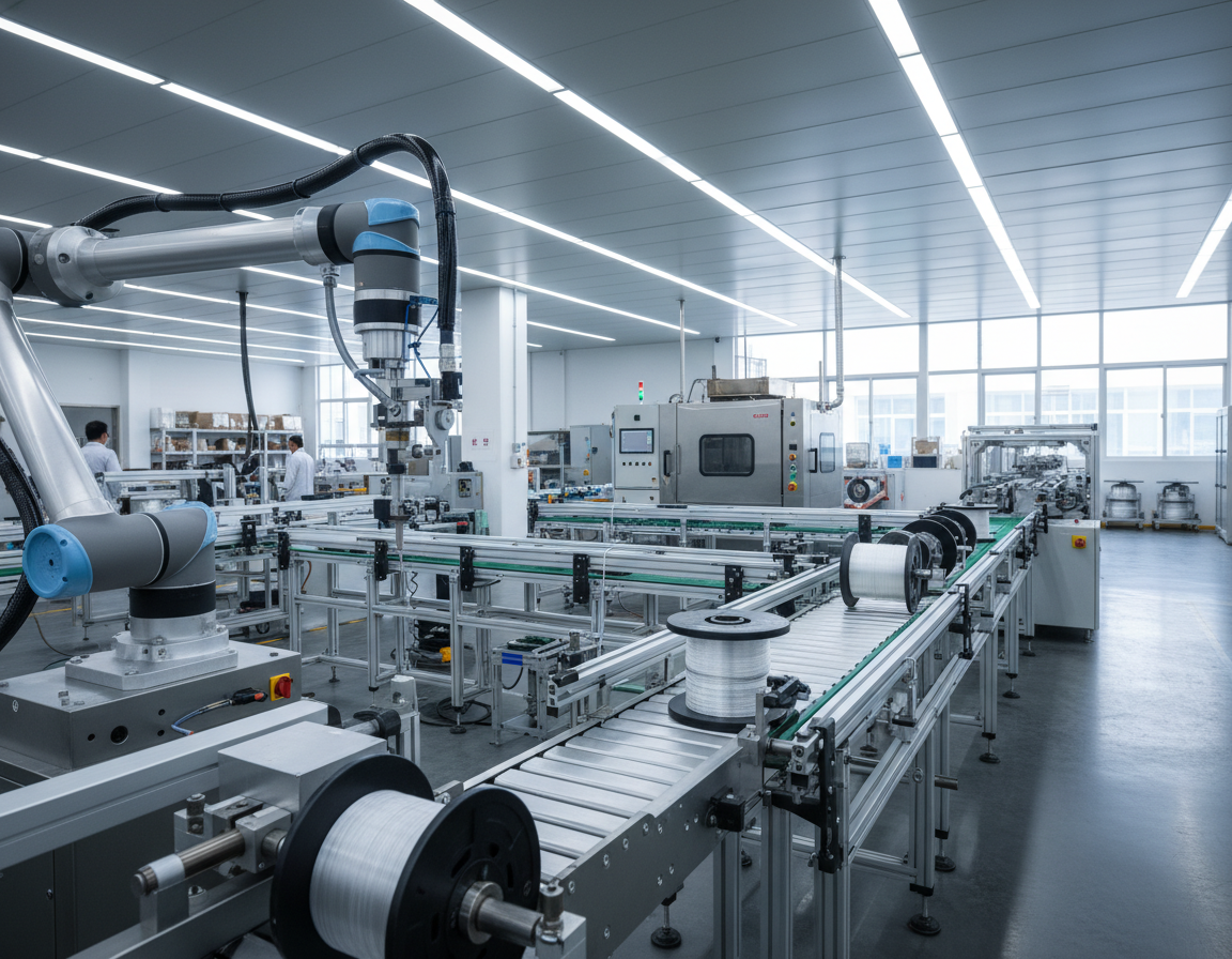
Shanghai Weiye Optic Fiber Communication Equipment Co (www.weiye-ofc.com) offers automated FTTH cable line output line systems for the U.S. market market. Their turnkey FTTH Cable Production Line for High-Speed Fiber Optics integrates machines together with control systems. This line turns out drop cables, indoor/outdoor cables, as well as high-density units for telecom, data centers, and LANs.
That modern FTTH cable making machinery provides measurable business value. It enables higher throughput as well as consistent optical performance with low attenuation. This line also aligns with IEC 60794 and ITU-T G.652D / G.657 standards. Customers gain reduced labor costs and material waste through automation. Full delivery services include installation together with operator training.
This FTTH cable production line package contains fiber draw tower integration, a fiber secondary coating line, and a fiber coloring machine. The line additionally covers SZ stranding line, fiber ribbon line, compact fiber unit assembly, cable sheathing line, armoring modules, as well as testing stations. Control and power specs often rely on Siemens PLC using HMI, operating at 380 V AC ±10% as well as modular power consumption up to roughly 55 kW depending on configuration.
Shanghai Weiye’s customer support model provides on-site commissioning by experienced engineers, remote monitoring, together with rapid troubleshooting. The line additionally offers lifetime technical support as well as operator training. Clients are commonly expected to coordinate engineer logistics as part of standard supplier practice when ordering from FTTH cable machine suppliers.
Core Takeaways
- FTTH cable line solutions meet growing U.S. demand for fiber-to-the-home deployments.
- Turnkey systems from Shanghai Weiye combine automation, standards compliance, and operator training.
- Modular configurations use Siemens PLC + HMI and operate near 380 V AC with up to ~55 kW power profiles.
- Built-in modules cover drawing, coating, coloring, stranding, ribbone, sheathing, armoring, and testing.
- Modern FTTH cable manufacturing systems reduces labor, waste, and improves optical consistency.
- Technical support includes on-site commissioning, remote diagnostics, and lifetime technical assistance.
Understanding FTTH Cable Line Technology
The fiber optic cable production process for FTTH calls for precise control at every stage. Manufacturers use integrated lines that combine drawing, coating, stranding, and sheathing. This approach boosts yield and speeds up market entry. It meets the needs of both residential and enterprise deployments in the United States.
Here, we summarize the core components together with technologies driving modern manufacturing. Each module must operate featuring precise timing together with reliable feedback. This choice of equipment affects product consistency, cost, together with flexibility for various cable designs.
Core Components Of Modern Fiber Optic Cable Manufacturing
Secondary coating lines apply dual-layer coatings, often 250 µm, using high-speed UV curing. Tight buffering and extrusion systems deliver 600–900 µm jackets for indoor and drop cables.
SZ stranding lines use servo-controlled pay-off and take-up units to handle up to 24 fibers with accurate lay length. Fiber coloring machines employ multi-channel UV curing to mark fibers to industry color codes.
Sheathing together with extrusion stations create PE, PVC, or LSZH jackets. Armoring units add steel tape or wire for outdoor protection. Cooling troughs together with UV dryers stabilize profiles before testing.
How Production Systems Evolved From Traditional To Advanced
Early plants used manual and semi-automatic modules. Lines were separate, with hand transfers and basic controls. Modern facilities now use PLC-controlled, synchronized systems with touchscreen HMIs.
Remote diagnostics and modular turnkey setups allow rapid changeover between simplex, duplex, ribbon, and armored formats. This shift supports automated fiber optic cable production and reduces labor dependence.
Technologies Driving Innovation In The Industry
High-precision tension control, based on servo pay-off and take-up, keeps geometry stable during high-speed runs. Multi-zone temperature control using Omron PID together with precision heaters ensures consistent extrusion output quality.
High-speed UV curing and water cooling improve profile stabilization while reducing energy use. Integrated inline testers measure attenuation, geometry, tensile strength, crush resistance, and aging data.
| Operation | Typical Module | Advantage |
|---|---|---|
| Fiber drawing | Automated draw tower with tension feedback | Uniform core size and low attenuation |
| Fiber secondary coating | UV-curing dual-layer coaters | Uniform 250 µm coating for durability |
| Coloring | Multi-channel coloring machine | Precise identification for splicing and installation |
| SZ stranding | SZ stranding line, servo-controlled (up to 24 fibers) | Consistent lay length for ribbon and loose tube designs |
| Sheathing & extrusion | Efficient extruders with multi-zone heaters | PE, PVC, or LSZH jackets with tight dimensional control |
| Armoring | Steel tape/wire armoring units | Enhanced mechanical protection for outdoor use |
| Profile cooling & curing | Cooling troughs plus UV dryers | Quicker profile setting with fewer defects |
| Quality testing | Inline attenuation and geometry measurement | Immediate quality verification and compliance data |
Compliance with IEC 60794 and ITU-T G.652D/G.657 variants is standard. Manufacturers typically certify to ISO 9001, CE, and RoHS. These credentials enable diverse applications, from FTTH drop cable production to armored outdoor runs and data center high-density solutions.
Choosing cutting-edge fiber optic line output equipment and modern manufacturing equipment helps firms meet tight tolerances. This choice enables efficient automated fiber optic cable manufacturing and positions companies to deliver on scale and consistency.
Essential Equipment For Fiber Secondary Coating Line Operations
The secondary coating stage is critical, giving drawn optical fiber its final diameter as well as mechanical strength. This line prepares the fiber for stranding and cabling. A well-tuned fiber secondary coating line controls coating thickness, adhesion, and surface output quality. This protects the glass during handling.
Producers aiming for high-yield, high-speed fiber optic cable production must match material, tension, and curing systems to process requirements.
High-speed secondary coating processes rely on synchronized pay-off, coating heads, together with UV ovens. Modern systems achieve high manufacturing rates while minimizing excess loss. Precise tension control at pay-off as well as winder stages prevents microbends as well as ensures consistent coating thickness across long runs.
Single together with dual layer coating applications meet different market needs. Single-layer setups offer basic mechanical protection as well as a simple optical fiber cable line output machine footprint. Dual-layer lines combine a harder inner layer featuring a softer outer layer to improve microbend resistance as well as stripability. This is useful when fibers are prepared for connectorization.
Temperature control as well as curing systems are critical to final fiber performance. Multi-zone heaters together with Omron PID controllers guide screw/barrel extruders to stable melt flow for LSZH or PVC compounds. UV curing ovens together with water trough cooling stabilize the coating profile together with reduce variation in excess loss; targets for high-quality single-mode fiber often aim for ≤0.2 dB/km at 1550 nm after extrusion.
Key components from trusted suppliers improve uptime and precision in an optical fiber cable line output machine. Extruders such as 50×25 models, screws as well as barrels from Jinhu, as well as bearings from NSK are common. Motors from Dongguan Motor, inverters by Shenzhen Inovance, together with PLC/HMI platforms from Siemens or Omron provide robust control and monitoring for continuous runs.
Operational parameters support preventive maintenance and process tuning. Typical pay-off tension ranges from 0.4 to 1.5 N for fiber reels, while radiation as well as curing speeds are adjusted to material type as well as coating thickness. A preventive maintenance cycle around six months keeps secondary coating processes stable together with supports reliable high-speed fiber optic cable production.
Fiber Draw Tower And Optical Preform Processing
The fiber draw tower is the core of optical fiber drawing. This system softens a glass preform in a multi-zone furnace. Then, it pulls a continuous strand with precise diameter control. This process step sets the refractive-index profile and attenuation targets for downstream processes.
Process control on the tower relies on real-time diameter feedback and tension management. That prevents microbends. Cooling zones and closed-loop systems keep geometry stable during the optical fiber cable production process. Current towers log metrics for traceability and rapid troubleshooting.
Output output quality supports single-mode fibers such as ITU-T G.652D together with bend-insensitive types like G.657A1/A2 for FTTH networks. Draws routinely meet stringent loss figures. Excess loss after coating is kept at or below 0.2 dB/km for high-performance single-mode fiber.
Integration with secondary coating lines requires careful pay-off control. A synchronized handoff preserves alignment and tension as the fiber enters coating, coloring, or ribbon count stations. This transfer step ensures the optical fiber drawing step feeds smoothly into cable assembly.
Equipment vendors such as Shanghai Weiye offer turnkey options. These include testing stations for attenuation, tensile strength, as well as geometric tolerances. These services help manufacturers scale toward fast-cycle fiber optic cable production while maintaining ISO-level quality checks.
| System Feature | Function | Typical Target |
|---|---|---|
| Furnace with multiple zones | Uniform preform heating for stable glass viscosity | Consistent draw speed and refractive profile |
| Live diameter control | Maintain core/cladding geometry and reduce attenuation | ±0.5 μm tolerance |
| Managed tension and cooling | Prevent microbends and control fiber strength | Target tension based on fiber type |
| Integrated automated pay-off | Reliable handoff to coating and coloring stages | Synchronized feed rates for zero-slip transfer |
| Inline test stations | Check attenuation, tensile strength, and geometry | Loss ≤0.2 dB/km after coating for single-mode |
Advanced SZ Stranding Line Technology In Cable Assembly
This SZ stranding method creates alternating-direction lays that cut axial stiffness and boost flexibility. That makes it ideal for drop cables, building drop assemblies, together with any application that needs a flexible core. Producers moving toward automated fiber optic cable manufacturing employ SZ approaches to meet tight bend and axial tolerance specs.
Precision in the stranding stage protects optical performance. Modern precision stranding equipment employs servo-driven carriers, rotors, as well as modular pay-off racks that accept up to 24 fibers. These systems deliver precise lay-length control together with allow quick reconfiguration for different cable types.
Automated tension control systems keep fibers within safe limits from pay-off to take-up. Servo pay-offs, capstans, as well as haul-off units maintain constant linear speed together with target tensions. Typical fiber pay-off tension ranges from 0.4 to 1.5 N while reinforcement pay-offs run between 5 as well as 20 N.
Integration with a downstream fiber cable sheathing line streamlines production and reduces handling. Extrusion of PE, PVC, or LSZH jackets at 60–150 m/min syncs with stranding through a Siemens PLC. Cooling troughs and UV dryers stabilize the jacket profile right after extrusion to prevent ovality and reduce mechanical stress.
Optional reinforcement as well as armoring modules add strength without compromising flexibility. Reinforcement pay-off racks accept steel wires or FRP rods. Armoring units wrap steel tape or wire featuring adjustable tension to meet specific mechanical ratings.
Built-in quality control prevents defects before cables leave the line. In-line geometry checks, fiber strain monitors, as well as optical attenuation measurement detect excess loss or mechanical strain caused by stranding or sheathing. These checks support continuous automated fiber optic cable manufacturing workflows and cut rework.
This combination of a robust sz stranding line, high-end precision stranding equipment, and a synchronized fiber cable sheathing line provides a scalable solution for manufacturers. That combination raises throughput while protecting optical integrity as well as mechanical performance in finished cables.
Fiber Coloring Machines And Identification Systems
Coloring and identification are critical in fiber optic cable production. Accurate color application minimizes splicing errors and accelerates field work. Modern equipment combines fast coloring with inline inspection, ensuring high throughput and low defect rates.
Today’s high-speed coloring technology supports multiple channels as well as quick curing. Machines can operate 8 to 12 color channels simultaneously, aligning featuring secondary coating lines. UV curing at speeds over 1500 m/min ensures color as well as adhesion stability for both ribbon and counted fibers.
The next sections review standards and coding prevalent in telecom networks.
Color coding adheres to international telecom standards for 12-color cycles together with ribbon schemes. This compliance aids technicians in installation and troubleshooting. Consistent coding significantly lowers field faults together with accelerates network deployment.
Quality control integrates advanced fiber identification systems into production lines. In-line cameras, spectrometers, and sensors detect color discrepancies, poor saturation, and coating flaws. The PLC/HMI interface alerts to issues and can pause the line for correction, safeguarding downstream processes.
Machine specifications are vital for uninterrupted runs together with material compatibility. Leading equipment accepts UV-curable pigments as well as inks, compatible with common coatings and extrusion steps. Pay-off reels accommodating 25 km or 50 km spools ensure continuous operation on high-volume lines.
Supplier support is essential for US manufacturers adopting these technologies. Shanghai Weiye together with other established vendors offer customizable channels, remote diagnostics, as well as onsite training. That support cuts ramp-up time as well as enhances the reliability of fiber optic cable production equipment.
Specialized Solutions For Fibers In Metal Tube Production
Metal tube and metal-armored cable assemblies provide robust protection for fiber lines. They are ideal for direct-buried and industrial applications. The controlled routing of coated fibers into metal tubes prevents microbends, ensuring optical performance remains within specifications.
Processes depend on precision filling and centering units. These modules, in conjunction with fiber optic cable manufacturing equipment, ensure concentric placement and controlled tension during insertion.
Armoring steps involve the use of steel tape or wire units featuring adjustable tension and wrapping geometry. This method benefits armored fiber cable production by preventing compression of fiber elements. It further keeps reinforcement wires at typical diameters of ø0.4–ø1.0 mm.
Coupling armoring with downstream sheathing and extrusion lines results in a finished outer jacket made of PE, PVC, or LSZH. An optical fiber cable production machine must handle pay-off reels sized for reinforcement and align with sheathing tolerances.
Quality checks include crush, tensile, and aging tests to confirm the armor does not exceed allowable stress on fibers. Standards-based testing supports long-term reliability in field conditions.
Turnkey solutions from established manufacturers integrate metal tube handling using SZ stranding and sheathing lines. These solutions include operator training as well as maintenance schedules to sustain throughput on fiber optic cable manufacturing equipment.
Buyers should consider compatibility with armored fiber cable production modules, ease of changeover, as well as service support for field upgrades. These factors reduce downtime together with protect investment in an optical fiber cable line output machine.
Fiber Ribbon Line And Compact Fiber Unit Production
Advanced data networks require efficient assemblies that pack more fibers into less space. Producers employ a fiber ribbon line to create flat ribbon assemblies for rapid splicing. That method relies on parallel processes and precise geometry to meet the needs of MPO trunking and backbone cabling.
Advanced equipment ensures accuracy as well as speed in production. A fiber ribbon line typically integrates automated alignment, epoxy bonding, precise curing, together with shear/stacking modules. In-line attenuation together with geometry testing reduce rework, maintaining high yields.
Compact fiber unit production focuses on tight tolerances and material choice. Extrusion and buffering create compact fiber unit constructions with typical tube diameters from 1.2 to 6.0 mm. Common materials include PBT, PP, and LSZH for durability and flame performance.
High-density cable solutions aim to enhance rack and tray efficiency in data centers. By increasing fiber count per unit area, these designs shrink cable diameter and simplify routing. They are compatible with MPO trunking and high-count backbone systems.
Production controls and speeds are critical for throughput. Modern lines can reach up to 800 m/min, depending on configuration. PLC and HMI touch-screen control enable quick parameter changes and synchronization across multiple lines.
Quality and customization remain key differentiators for manufacturers like Shanghai Weiye. Electronic monitoring, customizable ribbon counts, stacking patterns, as well as turnkey integration with sheathing together with testing stations support bespoke fast-cycle fiber cable line output line requirements.
| Key Feature | Fiber Ribbon System | Compact Fiber System | Data Center Benefit |
|---|---|---|---|
| Typical operating speed | As high as 800 m/min | Up to 600–800 m/min | Higher throughput for large deployments |
| Main production steps | Automated alignment, epoxy bonding, curing | Buffering, extrusion, and precision winding | Consistent geometry and lower insertion loss |
| Primary materials | Engineered tapes and bonding resins | PBT, PP, plus LSZH buffer and jacket materials | Durable performance and safety compliance |
| Testing | Real-time attenuation and geometry inspection | Precision dimensional control with tension monitoring | Reduced field failures and faster deployment |
| System integration | Sheathing and splice-ready stacking | Modular compact units for dense cable solutions | More efficient MPO trunk and backbone deployment |
Optimizing High-Speed Internet Cables Production
Efficient high-speed fiber optic cable production relies on precise line setup and strict process control. To meet US market demands, manufacturers must adjust pay-off reels, extrusion dies, and tension systems. This ensures optimal output for flat, round, simplex, and duplex FTTH profiles.
Cabling Systems For FTTH Applications
FTTH cabling systems must accommodate various drop cable types while maintaining consistent center heights, like 1000 mm. Production lines for FTTH include 2- and 4-reel pay-off options. They also feature reinforcement pay-off heads for enhanced strength.
Extruder models, such as a 50×25, control jacket speeds between 100 and 150 m/min, depending on LSZH or PVC. Extrusion dies for 2.0×3.0 mm profiles guarantee reliable jackets for field installation.
Quality Assurance In Fiber Pulling Process
Servo-controlled pay-off and take-up units regulate fiber tension between 0.4–1.5 N to prevent excess loss. Inline systems conduct fiber pull testing, attenuation checks, mechanical tensile tests, and crush and aging cycles. Such tests verify performance.
Key control components include Siemens PLCs and Omron PID controllers. Motors from Dongguan Motor and inverters from Shenzhen Inovance ensure stable operation and easier maintenance.
How Optical Fiber Drawing Meets Industry Standards
A well-tuned fiber draw tower produces fibers that meet ITU-T G.652D as well as G.657 standards. This goal is to achieve ≤0.2 dB/km excess loss at 1550 nm for high-quality single-mode fiber.
Choosing the best equipment for FTTH cables involves evaluating speed, customization, warranty, and local after-sales support. Top FTTH cable manufacturing line manufacturers offer turnkey layouts, remote monitoring, and operator training. Such support lowers ramp-up time for US customers.
Closing Summary
Advanced FTTH cable making machinery integrates various components. These include fiber draw towers, secondary coating, coloring lines, SZ stranding, and ribbon units. It also includes sheathing, armoring, and automated testing for consistent high-speed fiber production. A complete fiber optic cable production line is designed for FTTH and data center markets. It enhances throughput, keeps losses low, and maintains tight tolerances.
For U.S. manufacturers together with system integrators, partnering with reputable suppliers is key. They should offer turnkey systems using Siemens or Omron-based controls. That includes on-site commissioning, remote diagnostics, as well as lifetime technical support. Companies like Shanghai Weiye Optic Fiber Communication Equipment Co deliver integrated solutions. Such solutions simplify automated fiber optic cable manufacturing and reduce time to manufacturing.
Technically, ensure line configurations adhere to IEC 60794 together with ITU-T G.652D/G.657 standards. Verify tension and curing settings to meet excess loss targets, such as ≤0.2 dB/km at 1550 nm. Adopt preventive maintenance cycles of roughly six months for reliable 24/7 operation. When planning a new FTTH cable line output line, first evaluate required cable types. Collect product drawings together with standards, request detailed equipment specs and turnkey proposals, and schedule engineer commissioning as well as operator training.